Procedures Details <Prev Next>

Tracing Plate Spectra

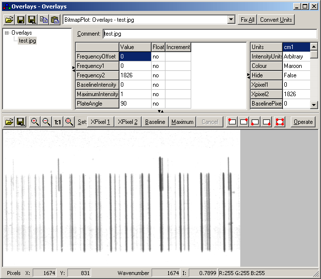
To trace a plate spectrum, first load the picture into the overlays window, so it looks something like the picture below. (You can load the picture by copying and pasting from another application or loading image files directly.)

1. Determining Plate Angle

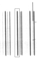
The plate is unlikely to be scanned perfectly vertically, and this is not a requirement for accurate operation. The angle must be measured, by selecting a single clear line with the mouse as follows:

Press "Operate" and then "Plate Angle" to display and set the plate angle. (It is recorded as one of the settings for the overlay.)

2. Select Region to Scan

Select the region to trace by pressing the following buttons in turn:
Set top left of region to trace
Set top right of region to trace
Set bottom left of region to trace
Set bottom right of region to trace
Set all four corners of region to trace
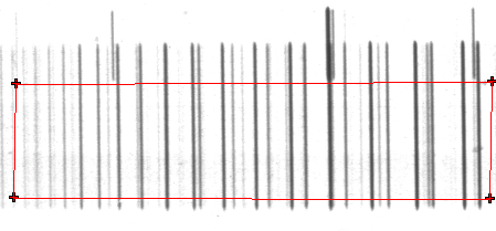
After pressing one of the above, press the mouse button on the required point. The "Cancel" button can be used to stop the process. The "Top" points define one edge of the trace area; the "Bottom" points are only used to define the line at which the trace stops. (The "Top" line does not have to be above the "Bottom" line.) To trace the main spectrum above the window should look something like this:

and for the calibration lines:


3. Perform the Scan

Select "Operate" and "Plate" to do the scan. An additional overlay will be generated each time you do this; the vertical scale is the average of the intensity along the lines determined by the plate angle. The horizontal scale is the pixel value where this line passes through the centre of the image, so that each spectrum traced from the same image will be on a consistent horizontal scale.

4. Calibration

The standard calibration procedure can now be used. Note that if you use separate calibration traces you should use "Apply Calibration To" to transfer the calibration from one overlay to another rather then "Copy Frequency to".