Windows <Prev Next>

Residuals and Intensity Residuals Window

These produce plots to assess the quality of a fit. There many possible forms for the plots, and in fact two possible residuals windows:
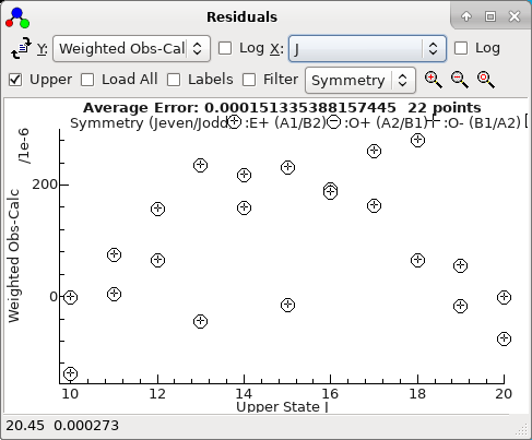
These will normally appear automatically when relevant, but can be shown with "View","Residuals" and "View","Intensity Residuals". The default residuals window will look something like this:
The status bar displays the x, y co-ordinates of the mouse and, if the mouse is over an experimental point, the source of the data point. Right click on the point for various options for working on observations; see below for a list. If you select an area with a mouse additional options applying to the points inside or outside the area are available.

If PGOPHER is correctly configured, you can go directly to the source of the data by right clicking on a given point and selecting "Edit Point" - see below for other options.

For the formulae below, oi is the ith observation, ci the corresponding calculated value, pi is a population and wi the weight. The population, pi, is the calculated population of the upper or lower state, depending on the setting of the Upper check box. The average error displayed at the top is simply [Σ[(oi-ci)/wi]2/nobs]½, which is slightly different to the value given in fits as it does not take account of the number of parameters floated. (This allows a value to be calculated without doing a fit.)
If fitting using the Log Window, reload observations and recalculate residuals, equivalent to doing a fit with no parameters floated. If fitting using the Line List Window, use the Test button instead.
Select the Y axis of the plot. Possible choices are:
  • Weighted Obs-Calc - (oi-ci)/wi
  • Unweighted Obs-Calc - oi-ci
  • Weighted (Obs-Calc)/Obs - The relative weighted error, (oi-ci)/(oiwi)
  • Unweighted (Obs-Calc)/Obs - The relative (unweighted) error (oi-ci)/oi
  • Observed - oi
  • Calculated - ci
  • Observed and Calculated - Plot oi as normal, with a line joining it to ci.
  • Weight - wi
  • Calc/Obs - ci/oi
  • Obs/Calc - oi/ci
  • Obs/Calc*Population - oipi/ci. For intensity fits, this is equivalent to the ratio of "observed" to calculated populations.
  • Obs/Calc*Population and Population - oipi/ci as above, but with a line joining the point to the calculated population.
  • Population - pi
  • Icentre - The experimental intensity at the observed position of the transition. This requires an Experimental Plot is loaded that is not a line list. The first suitable one is taken, which will be the uppermost in the Overlays Window or the lowest in the main window.
  • Icentre/Icalc - The ratio of Icentre calculated as above to the calculated line intensity.
  • Icentre/Icalc*Population - The ratio as on the previous line multiplied by pi.
The plots towards the bottom of the list are particularly useful when fitting intensities.

Take log (to base 10) of preceding axis.
Select the X axis of the plot. Possible choices are:
  • Observation Number - i
  • Frequency - The position of the transition; typically the same as oi, except for intensity fits.
  • State Energy - The energy of the upper or lower state of the transition, depending on the Upper check box.
  • Calculated - ci
  • Observed - oi
  • Weight - wi
  • Population - pi
  • Iobs - The observed intensity, if present in the fit input.
  • Icalc - The calculated line intensity.
  • J
  • N
  • F
  • A: Ω for linear molecules, |K| for symmetric tops, Ka for asymmetric tops
  • A + J/Jmax
  • J + A/Amax
  • B: F1, F2...for linear molecules, Kl for symmetric tops, Kc for asymmetric tops
  • B + J/Jmax
  • J + B/Bmax
  • F1 Hyperfine quantum numbers (if appropriate)
  • F2
  • ...
  • F9
Note A and B above will normally show as the appropriate quantum number, unless multiple types of molecules are being simulated.
Check to use upper (rather than lower) state quantum numbers, symmetry, energy and population (pi).
Plot data with zero weight (which would otherwise not be plotted).

Show boundaries between:
  • Files if the observations span more than one file and the X axis style is Observation Number.
  • Branches if the observations are all from the Line List Window and are grouped by branch.
Symbol Choose how to select the mark styles:
  • Symmetry - A different mark for each state symmetry.
  • Delta J - A different mark for each change in J. This is always upper J - lower J.
  • Error Bars - plot wi as error bars.
Filter Select plotted transitions using the Transition Selection and Details Window.
Zoom into region selected with mouse.
Zoom plot out.
Reset plot to fill window.

Popup Menu Items

To bring up this menu right click on the point(s) of interest Draw a box with the mouse before right clicking to operate on multiple points.

Edit Point Prepare point under cursor for editing:
  • If the observation is in the Line List Window that line is selected in the line list window. You can edit the text in the line list window, or right click and drag on the experimental spectrum to reassign the line.
  • If the observation is in an external text file, then the file is opened with the TabSlave Editor (if set up correctly) and the cursor positioned on the line containing the observation.
  • If the observation is in another .pgo file, start a second instance. of PGOPHER (if a second instance of PGOPHER is not already running) and invoke "Show and Edit" as below in that instance.
Show Transition Shift main plot to show transition that the indicated point derives from. (You may want to expand the plot several times to show the detail.)
Show and Edit Perform both actions above.
Clear Point(s) Set* weight of points under cursor to zero.
Clear Points Inside Set* weight to zero for points inside the region selected by the mouse.
Clear Points Outside Set* weight to zero for points outside the region selected by the mouse.
Delete, Delete Point(s) Delete* points from line list.
Delete, Delete Points Inside Delete* points inside the region selected by the mouse.
Delete, Delete Points Outside Delete* points outside the region selected by the mouse.
Copy to clipboard Use Paste Special to paste picture or underlying data (if available) in the target application
Print... Show print preview and allow print of plot
Export to file... Export plot to external file
Font... Choose font for graph text
Variable Char Size Character size on printer and clipboard depends on window size
Limit Line Segments Limit number of segments on a plotted curve. Leave this checked unless you have problems with the graph when printed or exported.
*Note that the Clear Points... and Delete Points... actions are currently only implemented for points in the Line List Window in the same instance of PGOPHER.