Valence Coordinates
The valence coordinates are closely based on
those described in L. Hedberg, I. M. Mills, J. Molec.
Spectrosc. 160, 117 (1993), and this should be
referred to for precise definitions and units. Any differences are
noted below.
The units of the coordinates are Å for the stretches and
radians for the others (all some form of angle), so the stretching
force constants have different units to the others.
Stretch
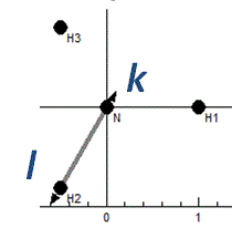
Bond length between atom k and l:
Bend
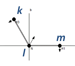
The angle klm:
Linear Bend
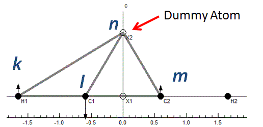
For atoms in a line an additional constraint
is required, and four atoms must be specified rather than three.
(The name is still bend in the internal
coordinates object.) In contrast to the Hedberg and Mills paper
the coordinate is taken to be the angle klm in plane of
atom n, rather than specifying a separate vector. The
extra atom, n, will typically be a dummy atom. (If the
atoms are not in a line an additional atom can still be specified;
formally the displacements are then parallel to the plane
containing k l and n.)
BondPlane
This is type 2 out of plane bending in the nomenclature of Hedberg
and Mills. It is the angle between bond kl and plane mkn.
The plane is indicated by a triangle in the plot:
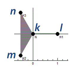
and the side projection shows the motion:

Plane
This is type 1 out of plane bending in the
nomenclature of Hedberg and Mills. Given centre (or apex) atom
k
and three other atoms in the same plane (
lmn) the
coordinate is the scalar triple product of unit vectors along
bonds:
ekl ● ekm
× ekn.
All the atoms are shown joined to the central atom:
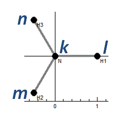
and again a different projection is needed to show the motion
Torsion
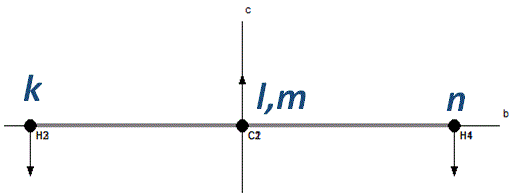
Given atoms klmn in a chain, the coordinate is the angle
between the planes klm and lmn. (The atoms klm
and lmn must not be collinear.) The chain is shown in the
plot window:
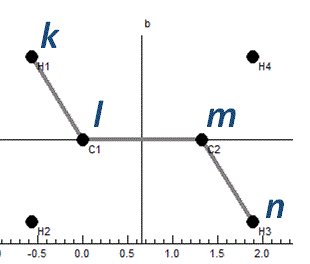
and a different projection shows the displacements:
Torsion (Generalised)
In an extension to the torsion as defined by
Hedberg and Mills above, a generalised torsion can be given by
only specifying two (bonded) atoms, kl for a torsion. The
valence coordinate is then an average of all possible 4 atom
torsions defined as above, identifying the bonded atoms from all
the other valence coordinates. (All the bonds indicated above are
counted, apart from the 4th atom in the linear bend.)
The plot window joins all the affected atoms:
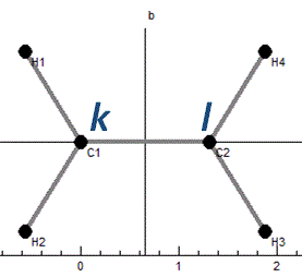
and again a different projection shows the displacements:


