Calibrating Spectra
PGOPHER can be used to calibrate an
experimental spectrum from anything displayed in the simulation
window; a line list or a simulation of a known spectrum are likely
to be the most useful sources. The following built in calibration
sources are available (see
File,
New, Calibration):
- The visible B-X absorption spectra of I2.
The line positions for this are calculated from the constants
given in F. Martin, R. Bacis, S. Churassy and J.
Vergès, J. Molec.
Spectrosc. 116,
71 (1986) with the Franck-Condon factors estimated from RKR
curves generated from these constants. Checks against high
accuracy measurements in H. Knockel, B. Bodermann, and E.
Tiemann, Eur.
Phys. J. D 28
199 (2004) indicates a maximum error of 0.043 cm-1,
but < 0.02 cm-1 for the v" < 11 transitions
typically used for calibration.
- Ne and Fe atomic lines with positions and intensities taken
from the NIST Atomic Spectra Database (version 3.0.3), Yu.
Ralchenko, F.-C. Jou, D.E. Kelleher, A.E. Kramida, A.
Musgrove, J. Reader, W.L. Wiese, and K. Olsen http://physics.nist.gov/asd3
[2006, June 18]. National Institute of Standards and
Technology, Gaithersburg, MD.
- A set of line positions for use with Ne optogalvanic
spectra, commonly used for calibrating pulsed dye lasers. The
lines are taken from "An atlas of optogalvanic transitions in
Neon" RAL report, RAL-91-069 (1991) by S.H. Ashworth and J.M.
Brown, with Ne lines from the NIST database (see above) and a
few points added from our own measurements.
If you have an etalon trace recorded with the data, then follow
the procedure in
Using Etalons to
produce a linear frequency scale, and then use (if necessary) the
procedure below to calibrate the resulting scale.
1. Load Experimental data and Calibration source
First load the experimental
spectrum and set up the reference source for the calibration, so
the simulation window looks something like the picture below; see
Overlaying Files for how to do this.
Note that both spectra should have upward pointing peaks; use
Overlays,Invert if necessary to invert your spectra
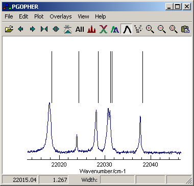
In this case the spectrum is atomic lines, and the upper trace is an
atomic line list.
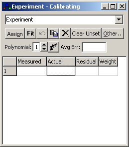
2. The Calibration Window
Use Overlays, Calibrate (or right
click on the experimental spectrum and select calibrate) to bring
up the
calibration window, and make
sure the experimental spectrum to be calibrated is selected in the
box at the top of the dialog:
Important:
While calibrating, there are two horizontal scales that need to be
considered:
- The original uncalibrated scale, perhaps the point number
for a simple experimental recording
- The new (tentatively calibrated) scale, typically frequency
or wavelength.
As you start calibrating, the plot will always be of the new
scale, but peak measurement and display changes for overlay
channels as follows:
- If the calibration dialog is open and selecting a particular
channel then peak measurements of that channel will be on the
original frequency scale.
- Otherwise peak measurements will use the new (hopefully
calibrated) scale.
In addition, while the calibration window is open, Alt+drag will
move the selected experimental spectrum rather than the
simulation.
Make sure the
calibration window is closed when you have finished calibrating
or you will be using an uncalibrated scale for peak measurements.
3. Initial Alignment
The traces need to be roughly
aligned to start with, at least so the assignment to the reference
spectrum is clear. If the experimental spectrum has an
approximately correct scale, then an offset may be sufficient -
alt + drag in the main plot window, provided the calibration window is open.
If you know the approximate limits of the experimental spectrum:
- Select "Other", "Set Range". This
will add two measured "peaks" at the very start and end of the
spectrum, and they will appear in the calibration window. (They
are set with a large standard deviation of 1000, implying a
large uncertainty in their values, so any subsequent assignment
of calibration peaks with the default standard deviation of 1
will essentially ignore these points)
- Enter the corresponding frequencies in the "Actual" column for
these two points.
- Ensure the polynomial value is 1, and press "Fit".
Alternatively, it is possible to manually edit the FrequencyOffset and FrequencyScale of the
Experiment overlay.
4. Assigning Peaks
To use specific peaks in the spectrum for calibration:
- Right click and drag across an
experimental peak; the peak position is measured and appears in
the first column of the "Calibrating" form.
- The "Actual" box next to it will turn red to indicate the
actual position to be filled in.
- Right click and drag across the
corresponding peak in the calibration spectrum; the position of
this will be filled in the square indicated above.
- Repeat as required - you will only need a few peaks in the
initial stages.
To correct mistakes:
- To cancel or re-do an assignment click the "Assign" button;
this is for re-doing steps 2 and 3 above.
- To delete entries use the "x" button
5. Fitting
Given some assignments, press the
"fit" button. The residuals will be filled in and the experimental
plot will be adjusted to reflect the newly fitted frequency scale.
The residuals will be plotted in a separate window.
- The undo fit button will step the
function and plot back one step,
- By default a linear function is
used; to use a higher order polynomial change the number in the
spin box. The details of the fitted function (the parameters
used, estimated errors and the correlation matrix) will be
displayed on pressing the button next to it; this also allows an
arbitrary function to be used for fitting.
- If you used the simulation offset
(The Offset box in the main window) to line up the simulation
and experimental traces, you will probably want to reset this to
zero after the first fit.
You will probably want to add more peaks - go back to step 4.
6. Transferring the Calibration
Once you have a suitable
calibration, you can transfer the calibration to another spectrum
using one of the following entries on the "Other" menu:
- Copy
Frequency To: This is for the common case of spectra
with a common x axis,
as when several signals are recorded simultaneously. (This
implies they have the same number of points.)
- Apply
Calibration To: This is for the more general case where
the spectra have independent x
axes, but the mapping between x
and frequency is the same for both spectra. (This will typically
apply to spectra recorded independently, and also plate spectra
are likely to be this way.) Note that the original x scale is lost on saving
in this mode.
In each case your are prompted to select the spectrum to apply the
calibration to; select "all" the default to apply it to all
overlays. Note that transferring a calibration of a spectrum onto
itself (or selecting all) has the effect of removing the original
frequency scale.
 Procedures