| |
<Prev Next> |
The internal coordinates object allows 3N-6 (or more) internal valence coordinates, R, to be set up which will be used to construct the matrix, B, that transforms between the 3N Cartesian displacements, Δx and R:
R = B Δx
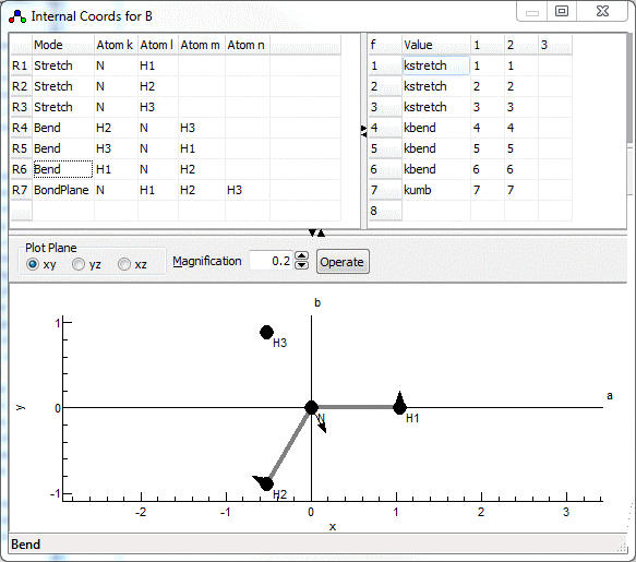
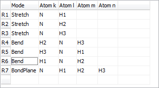
Redundant valence coordinates can be specified (i.e. more than 3N-6), though this imposes some constraints on the possible calculations. The internal coordinates window, shown below for NH3 in a planar configuration, allows the display and editing of the valence coordinates and (optionally) the force field in terms of valence coordinates. To create an internal coordinates object, right click on the Electronic State object object and select "Add New..., Internal Coords". To bring up the window right click on the internal coordinates object and select "View...".

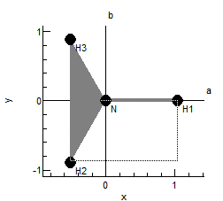
The plot at the bottom shows the current internal coordinate, i.e. the selected row in the top left grid. The arrows indicate how far each atom moves, and the atoms involved are linked by thick gray lines. The plot updates semi-automatically; use "Operate, Check" to force an update.


| Check |
Check the contents of the top grids, and
update the plot to match |
| Print |
Check the contents of the top grids, and
display the details of the vibrational mode calculation in
the Log Window. |
| Make
Extra Operators |
Create vibrational perturbations - see Other Potential Terms
below. |
| Show
VIBCA file |
Writes a data file for the VIBCA
program to the Log Window. See http://www.ifpan.edu.pl/~kisiel/vibr/vibr.htm;
note that not all PGOPHER files can be converted. |
| Calculate f Matrix from l | Print the f matrix in the Log
Window calculated from the l matrix
elements and frequencies given in the vibrational mode objects.
This is only possible if there are no redundant internal
co-ordinates. If this is not the case, the calculation must
be done via symmetry coordinates and the F matrix. |
| Set f Matrix from l | Clear the f matrix grid (top right) and set it from the l matrix elements and frequencies given in the vibrational mode objects. This is only possible if there are no redundant internal co-ordinates. If this is not the case, the calculation must be done via symmetry coordinates and the F matrix. |
| Calculate f matrix from F matrix | Print the f matrix calculated from the F
matrix using the following equation:f = UT F U |
| Set f matrix from F matrix | Clear the f matrix grid (top right) and set it by
calculation from the F matrix using the following
equation:f = UT F U |
| Sort f Matrix by Value | Sort the f matrix grid (top right) in descending order of the first column. |
| Sort f Matrix by Mode | Sort the f matrix grid (top right) by mode numbers, with diagonal elements first. |

V = ½ RT f R = ½ Σij fijRiRj
| Units |
|
| Stretch-Stretch |
millidyne/Å = aJ/Å2 |
| Stretch-Bend |
millidyne/rad = aJ/(Å rad) |
| Bend-Bend |
millidyne Å/rad2 = aJ/rad2 |
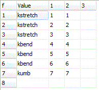
The force constants can be given as simple numerical values, but can also be given as general expressions involving symbolic values. This is typically more useful, as it allows symmetry constraints to be added naturally. For the NH3 example shown here, note the use of three different force constants, kstretch, kbend and kumb for each of the three different types of internal coordinate. The force constants can be given as general expressions if required; the common usage of scaling ab initio force constants could be done by expressing the constants as kscale*kstretch, and so on, with kscale initialized to 1.When reading the force constant matrix, unknown variables are automatically created as parameters to the current internal coordinates object, and they can then be edited in the Constants Window. If dealing with more than one isotopologue, these variables are better placed in a variables object, (with Global set to true) so the same value can be used in all species.
Note that the force constant grid will expand automatically as atoms are added. The grid can be left blank if the potential energy is to be expressed in terms of symmetry coordinates.The electronic states on which the potential terms act can also be specified as part of the force constant matrix, allowing terms acting between electronic states to be handled, such as those involved in the Jahn-Teller effect. This is done by adding, on the end of the row of the force constant matrix, the states names as a bra and ket, such as <B+|B->. If the state name is omitted, the state the internal coordinates object is under is assumed. Such force constant terms are not included in determining the normal modes, but the corresponding terms in dimensionless normal coordinates (found by transforming the force constants with dint) will be given as part of the standard print outs. In addition they will update any vibrational perturbation objects that match. See The Jahn-Teller effect in the B state of NH3 for a worked example.
Important: The perturbation objects are not created
automatically, but only when the Make Extra Operators menu
item is used. Any perturbation updated from these other
potential terms will have FromForceField
set to true, requiring the value of the perturbation to come
from the force field.
Linear potential terms can be specified by just giving one
index, with a contribution to the potential of
V = f(1) R = Σi f(1)iRi
The units are aJ/Å or aJ/rad. These will only affect
subsequent calculations if linked to a perturbation object as
above, though the corresponding linear terms in dimensionless
normal coordinates (= f(1) dint)
will be given as part of the standard print outs.

| Active | Set true to use this internal coordinates object; there
must be no more than one active internal coordinates object
at a time. |
| InPrincipalAxis | Toggles selected calculations between the principal axis
system and the axis system used in the z matrix specification. |